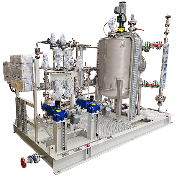
 Dynapumps has fully designed, fabricated, and tested an Anti Foam Injection Package for an LNG onshore project. This package includes two duty/stand-by Bran + Luebbe H1 Novados pumps with Toshiba 0.37kW 4Pole motors fully tested and designed to API 675. These pumps are manifolded together with small DN15 & DN25 stainless steel pipework and connected to an 830L AS1210 stainless steel mixer tank, all pipework, mixer tank, and baseplate have been fabricated by Dynapumps.
The mixer tank is supplied with an SPX Lightnin Mixer connected to a Toshiba motor, magnetic level gauge, guided wave radar level transmitter, DN300 access nozzle, vent, and 5 other connections for process inlet and outlet connections.
This system is designed to allow for the mixing of 1 part water from the main process water feed with 3 parts anti-foam which is pumped via a Lutz MD2 drum pump with NIRO-41 air motor from a drum located on-site next to the skid. This drum pump and hose connection to the mixer tank has been supplied by Dynapumps along with an air line with a pressure regulator/gauge to be installed on-site by others to supply power to the air motor. Once this antifoam has been mixed inside the tank it is pumped by the main Bran + Luebbe pumps into the system as required.
The entire system is mounted on a common painted base frame to API675 standard, with a full drip tray under all components and galvanised grating to allow easy access to all components. The suction line after the mixing tank is manifolded with the line to each pump containing a y-strainer and ball valve.
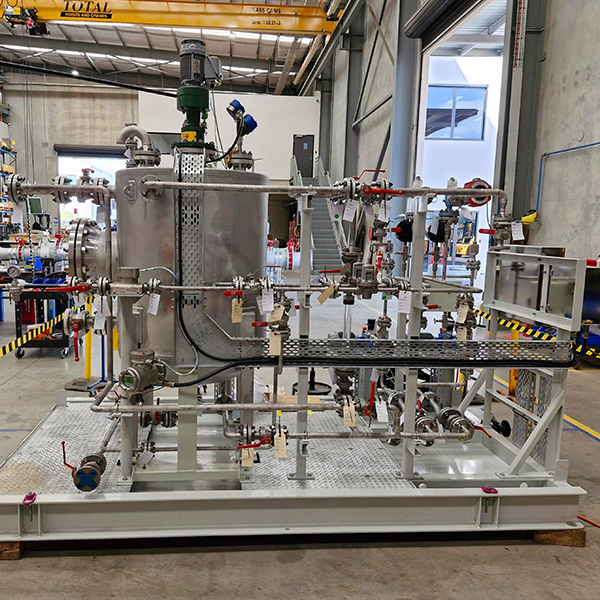 Prior to the split to each pump, there is a calibration column used to test the pumps and check that they are properly calibrated. The discharge line is also manifolded with each pump line containing a Pulsation Dampener, a Ball Valve, a Pressure Control valve, and a 112mm pressure gauge. A flow meter is connected after the pumps are manifolded. A pressure relief valve is supplied for each pump with this relief line going back into the mixing tank.
The pipework also contains an elaborate drain network with all drains from the mixing tank, magnetic level gauge, and 4 drains from the discharge pipework manifolded together into a single drain line. A bypass pipework line is also provided that connects the main process water line to the pump suction line bypassing the mixing tank.
Whilst the control of the system is done by others the electrical team has provided a junction box to provide termination of all instruments on the skid along with a push button station that provides manual start and stop buttons for each pump and mixer motor as well as an emergency stop button for each motor and the ability to switch each motor from manual or automatic control.